- #Stm32 nucleo development board install
- #Stm32 nucleo development board software
- #Stm32 nucleo development board download
- #Stm32 nucleo development board free
Each part will be represented by the physical “footprint” that you assigned to it, and the pads on those footprints will have lines drawn between them to highlight connections which still need to be made between parts.

PCB Layoutįinally, the last step is to import the combined schematic and “footprint” data onto a grid which is measured in physical units like inches or millimeters.

This step will not be necessary in this tutorial and I will be skipping it to keep things simple, but it is useful if you need to use oddly-shaped parts. Similar to the abstract schematic parts, if KiCAD does not have a “footprint” file available for a physical part, we can create one.

The shape and size of a part will determine what its “footprint” should look like on the circuit board we want to expose copper on the board at the places where we want to solder parts on, so it is important that those copper pads and holes are correctly placed depending on the size of each part. Once we have a complete abstract circuit, we need to tell KiCAD what each part will look like in the real world. This is often necessary if you use integrated circuits, because there are just too many chips available to keep up-to-date entries for all of them in the default libraries. If KiCAD does not have a schematic file available for one of our parts, we can create one. In a program like KiCAD, we will define our schematic by placing each part on a grid, and then linking those parts’ connectors together with wires drawn on the same grid. If you’ve worked with electronics before, you will probably be familiar with the way that schematics are used to describe an electronic circuit. The first step in designing a printed circuit board is defining the abstract circuit that we want to lay down on the board. The process of designing a board in KiCAD typically follows these general steps – I’ll try to describe each one briefly before we get started: Schematic Capture
#Stm32 nucleo development board install
You may also have to install a “KiCAD Extras” package to use the default libraries and footprints. It has matured into an accessible and powerful tool, and it is still under very active development with the occasional new feature being added.
#Stm32 nucleo development board download
You can download and install the whole thing from their website your package manager might also have it available, but that could be an old version and KiCAD has improved a lot over the past couple of years.
#Stm32 nucleo development board free
KiCAD is a free and open-source suite of “EDA” (Electronic Design Automation) programs. The design files described in this post are all available in a Github repository, if you want a reference to follow along with. Right: OSHPark’s renders of the front and rear of the board.

Left: A board like the one you’ll design in KiCAD. But on the other hand, our board will be smaller and cheaper, and you will be able to put the same design onto more holistic boards with other parts for your kickass robot or electronic vehicle or : Our board won’t be quite as nice as ST’s, and it will require an external USB device for programming and debugging.
#Stm32 nucleo development board software
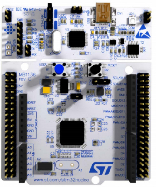
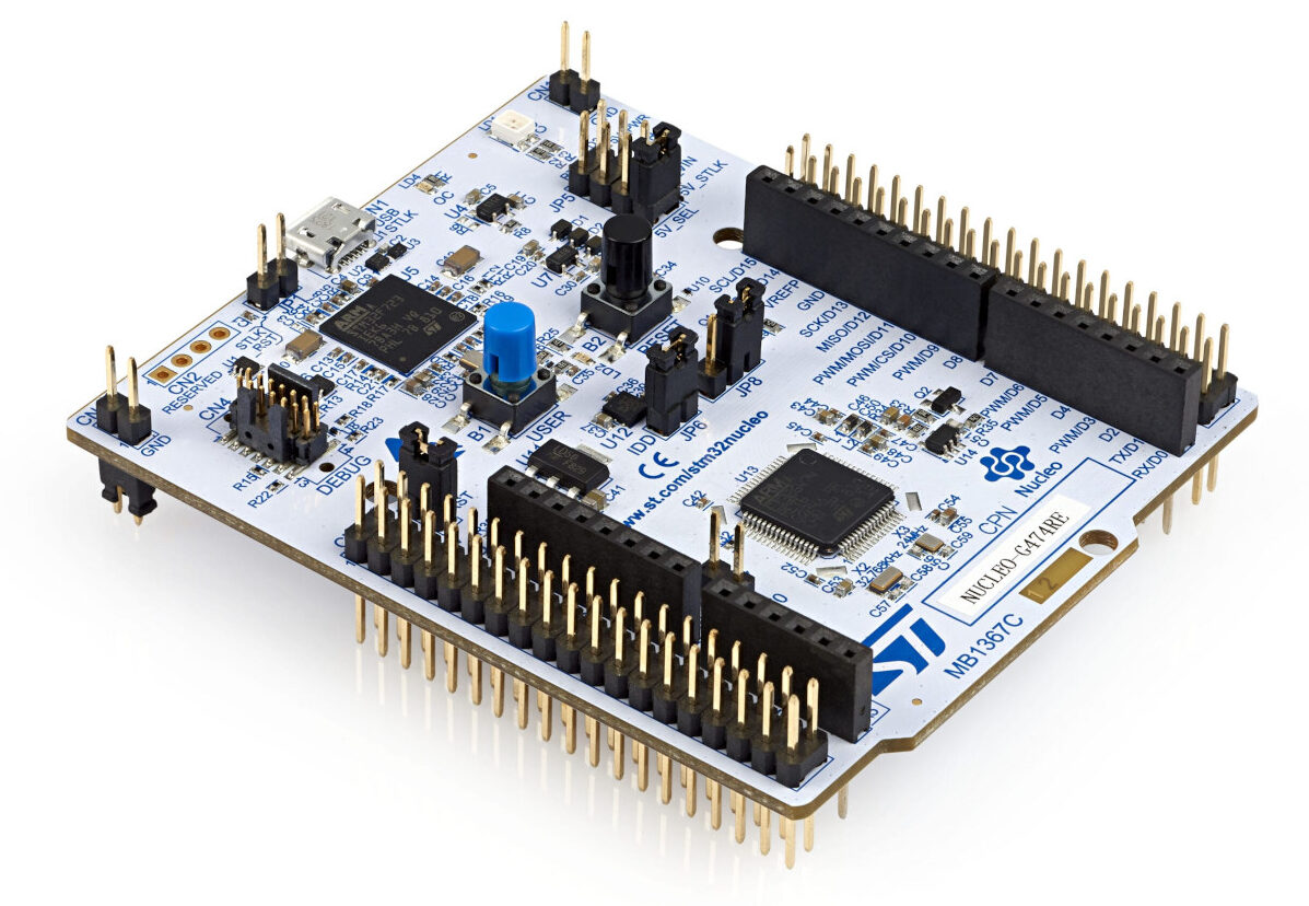
In this tutorial, we will use a suite of free software called KiCAD to produce a small example board using the same basic STM32F031K6 chip that I’ve been writing programming examples for. Still, the boards that we design in this tutorial will cost less than $2 each. The catch is, they usually take a few weeks to arrive and you need to provide the design. That’s a great way to get started and test ideas out, but what if you want to try your hand at building a robot, or a home automation widget, or some other sort of complex machine? It’s nice to avoid huge messes of breadboards and wires once you have a basic prototype working, and these days it only costs a few dollars to get a small custom circuit board manufactured. And along those lines, I’ve been writing a few tutorials about bootstrapping some basic ‘bare metal’ STM32 projects using an STM32F031K6 “Nucleo” board sold by ST. It’s great to be able to write programs for a chip’s evaluation boards, but the real strength of microcontrollers is their ability to act as a low-cost, low-power “brain” for larger designs or products.


 0 kommentar(er)
